By Jim Price
Introduction
I live in a circa 1950’s house that has forced air heating. Additions and have been made with better envelope performance therefore increasing the furnace heating output has never been required. After remodeling our kitchen and extending in to the former dining room we installed a ceramic tile floor. It can feel cold in the mornings and most of the winter because I don’t let the thermostat to go higher than 68° and the basement is un‑heated.
Existing Conditions
Our house is heated with a two‑stage condensing gas furnace. Years ago the highstage stopped working and the low‑stage 40 MBH was always enough to heat our house. (less than 20 Btu/sqft-hr). Our domestic water is heated with a direct vent hot water tank style heater. The total input capacity is 24 MBH. This is more than adequate if we schedule things wisely.
Design
The plan was to use the existing domestic water heater to provide heat for the kitchen floor. Following advice from George (who did this a few years ago) a heat exchanger would be used to separate the city water from the circulated heating water. There was a lot of scaling that occurred in a single season. This will require two pumps and a brazed plate heat exchanger. He also recommended having provisions to flush out the domestic side of the heat exchanger.
I calculated the heating load lost through the envelope components in the kitchen. This came to 3600Btu/hr. I used both a hand calculation and software to get nearly same results. Then I determined the net radiating surface area of our floor to be 229 square feet (cabinets, refrigerator and dog excluded). Dividing the heat output required with the emitting surface available I got a required heat flux 15.72 W/sqft-hr. I had to get out my heat transfer book to recall how radiation was calculated. The following assumptions were made:
I calculated the heating load lost through the envelope components in the kitchen. This came to 3600Btu/hr. I used both a hand calculation and software to get nearly same results. Then I determined the net radiating surface area of our floor to be 229 square feet (cabinets, refrigerator and dog excluded). Dividing the heat output required with the emitting surface available I got a required heat flux 15.72 W/sqft-hr. I had to get out my heat transfer book to recall how radiation was calculated. The following assumptions were made:
- The emissivity of the ceramic tile floor was 0.9
- The emissivity of the surrounding surfaces was based on painted surfaces and 0.9 was used.
- I used a normal factor of 1 for the calculation (the floor surface has views to a surface that should be heated in the kitchen). This also made the math much easier.
- I used a constant emitting surface temperature assuming the warmer spots will average out to match the colder spots.
The equation I used was:
Heat transfer = emission from floor – emission from the surroundings.
Or
=Floor area X Planck’s Constant X [floor emissivity X (avg floor temp)^4 – surr emissivity X (surr temp)^4]
The book I had used metric units so I had to convert the temperatures to Kelvin (absolute temperature) and sqft to square meters. Then I converted back from Watts to Btu/h. I made this calculation in a spreadsheet and used the solver to determine what average floor temperature would get exactly 3.6 MBH. The result was a temperature of 82°F. That would feel great on a winter day even with bare feet. Our dog should also find it nice and comfortable this next winter.
The heat from the floor had to match up with the heat conducted through the tubing and the heat from the heat exchanger.
I determined the conductance of the materials the heat moved through. It was mostly series conduction. The path was through:
- PEX tubing 23.3 Btu/sqft-hr-°F
- Wood subfloor 0.7212 Btu/sqft-hr-°F
- Thinset mortar 32.1775 Btu/sqft-hr-°F
- Porcelain tile 4.161 Btu/sqft-hr-°F
The resulting conductance was 1.7 Btu/sqft-hr-°F or an R value of 0.588. I divided the 15.72 Btu/h-sqft heat flux by the conductivity to get a temperature differential of 9.24°F. The average water temperature circulating beneath the floor is 9.24 + 82.0°F = 91.24°F. I arbitrarily chose a flow rate of 0.4 gpm for the floor loop. This will allow two circuits of 0.2 gpm to move through a 200 foot loop of tubing at a reasonable pressure drop. The water loop temperature drop is 18°F = 3600 Btu/hr /500 / 0.4 gpm. The maximum water temperature would be 91.24+(18/2)=100.24°F; after adding 5°F to account for a heat exchanger approach the minimum water temperature setting on the domestic water heater is 105°F (still safe in a house with kids).
Sizing the loop side pump:
Using the 200 foot loops of tubing and adding the pressure loss of the hydronic components the pump needed to be 17.4 feet at 4gpm. I sized the pumping system and heat exchanger to handle the entire first floor in the future (around 20 MBH). The pump will be throttled until the future circuits are connected.
Sizing the domestic pump:
Using published data from the heat exchanger
I drew up heating plant plans and shopped for the components. The parts included were:
|
|
I thought it would be a great idea to have the domestic (hot-side) of the also function as a domestic hot-water recirculation system. Domestic hot water will enter the ‘heating plant’ from the hot water recirculation lines at the upper floor bathrooms and then exit to the bottom of the domestic hot water heater through the drain valve where a tee was added. I will rig a timer up to the domestic water pump relay to get it to function as a hot water recirculation system.
Construction
I first started installing the tubing. I drilled 1.25” diameter holes across through the top portion of the floor joists. This allows two tubes per joist (out and back) typically. This allowed the tubing to run out and back in each joist bay. There are plenty of tricks out there that can be googled to make it easier. The worst thing that you could do is kink the tubing during the installation; I did it twice. I was using PEX type ‘a’ tubing which is much easier to repair than using the other types. It will get repaired when I run hot water through it. I could also heat it with a heat gun or powerful hair dryer to reset to the original structure. Other PEX tubing types requires cutting and replacing damaged sections. I used nailing clips to hold the tubing tight to the subfloor.
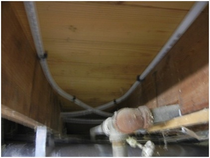
The black clips were nailed into the subfloor. Notice the floor joist that was notched (probably by a plumber) to provide a path for the 1” galvanized pipe
Much of the subfloor was tongue and groove board; as I hammered fifty years of dirt fell out of the cracks. I made sure to not heat the floor beneath the refrigerator and didn’t bother to install tubing beneath the kitchen cabinets. One major difficulty I had was working the tubing in the joist bays that had ductwork. If this was a new build the ductwork would go in after the PEX was installed. I removed and re-installed the ductwork in most cases. I installed r-13 fiberglass battinsulation into the joist pockets after the tubing was installed. This left a 2” gap between the subfloor and the insulation as recommended by most installers. It would keep a warm air pocket and avoid direct conduction through the insulation. Some people recommend using a reflective surface to prevent radiant transfer. I thought that would be an ineffective measure because of the debris that will continue to fall from the tongue and groove board cracks in the subfloor. I replace the joist cross bracing with solid blocking to firm up the floor and allow straight tubing runs.
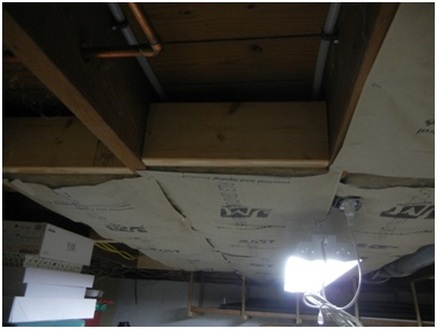
Looking at the photo you can see the solid wood blocking installed
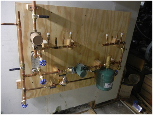
Building the ‘heating plant’ was much easier than installing the tubing in the joist bays. Basically following the plans I connected the components and anchored them onto a piece of ¾” plywood. Instead of buying bell hangers, I made then with 2x4 wood and copper straps. Some of the components were far out of plane and I cut a hole in the back of the board for the heat exchanger to fit through. Using a stainless steel heat exchanger and copper pipe raised concern about dissimilar metals and galvanic corrosion. I planned to use dielectric unions to eliminate the risk. Unfortunately it was impossible to fit two unions next to each other. I settled for dielectric unions on the potable water side and easy to change out shark-bite fittings on the loop side. I made sure to keep the Loop return water enters on the right hand side of the ‘heating plant’ and leaves through the manifold on the left hand side. Notice the green expansion tank below the air separator and the green loop pump. Domestic hot water from the domestic return loops heater enters the ‘heating plant’ through the vertical tube on the far left. The tan pump circulates domestic water through the heat exchanger and back to the hot water tank drain valve outlet. Notice the extra boiler drain valves installed to permit a heat exchanger chemical flush.
Commissioning
The expected completion date will be after the heating is required. I will heat up the floor anyways to test it out. Check back next fall to see how it works.

 RSS Feed