To begin to understand the principles of energy savings with occupant comfort, one must understand the concept of pressure independent systems couple with variable frequency drives (VFDs). VFDs are utilized in both air side and wet side applications, but for this application we will be discussing hydronic systems. In short, a VFD enables a hydronic system to operate more efficiently through multiple pump system curves versus the age-old method of single speed pumping with modulating pressures (substantially less efficient).
Joe Stagg - Pipeline Development Company
I met
Joe earlier this month at a training seminar for the pump manufacturer that I represent outside of Atlanta. His company,
Pipeline Development Company, shares a similar motive with HVACLive in their intent to provide
free, un-biased education to the HVAC industry. Through on-site training classes or webinars he offers continuing education and PDH credits.
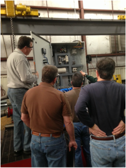
When he began his presentation he talked about his role as an educator and how he taught classes on systems/products without directly promoting the affiliation for which he had been sponsored by. He has a background as a sales representative and I found his approach intriguing.
His experience and education background led to the simplest and easiest presentation that I've ever attended when it comes to hydronic systems. The best way for you to understand this topic is to hear it first hand for yourself directly from Joe.
Click
here, and enjoy...
By Jim Price
Introduction
I live in a circa 1950’s house that has forced air heating. Additions and have been made with better envelope performance therefore increasing the furnace heating output has never been required. After remodeling our kitchen and extending in to the former dining room we installed a ceramic tile floor. It can feel cold in the mornings and most of the winter because I don’t let the thermostat to go higher than 68° and the basement is un‑heated.
Existing Conditions
Our house is heated with a two‑stage condensing gas furnace. Years ago the highstage stopped working and the low‑stage 40 MBH was always enough to heat our house. (less than 20 Btu/sqft-hr). Our domestic water is heated with a direct vent hot water tank style heater. The total input capacity is 24 MBH. This is more than adequate if we schedule things wisely.
Introduction
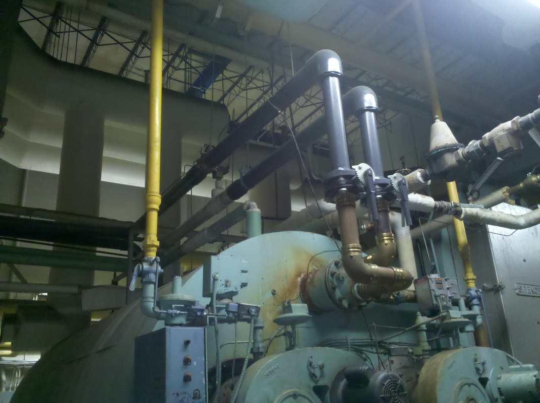
MJ Mechanical is in the process of redesigning the existing system that provides heat and hot water for a large building for one of our customers. The building contains office space requiring domestic water (showers, sinks) as well as a swimming pool for the occupants. Our redesign of the existing system required an energy analysis of the current setup in order to be able to size the new
equipment, and to calculate the capacity of the replacements. For the purpose of this case study, we will look at the domestic hot water/pool heating analysis of the project.
UPDATE - 02/07/2012
Cannon Design has just informed us that this project successfully achieved a LEED Gold certification, an upgrade from the LEED Silver that was originally achieved. See more on this project HERE About
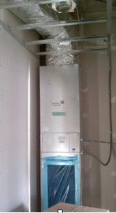
Design began on the Buffalo State Housing building in 2009 and the building was complete for the Fall Semester of 2011. Restrictions/goals on this project included budget and LEED certification, which can be somewhat conflicting goals.
The building was divided into typical 4 bedroom suites including kitchens and living rooms with some studio and RA/RD suites interspersed. Each suite is equipped with its own heat pump for individual temperature control. These suites are typical and stacked through each floor of the building, so the loop water is routed through each of the top floors of the wings and follows the heat pump stacks down to the lower floors. This proved to be a very efficient way of routing the loop water.
System Selection

After analysis of various HVAC strategies including fan coil units,
PTACS, and variable air volume systems,
heat pumps were chosen as an appropriate system because of their efficient nature and ability to do simultaneous heating and cooling. A VAV system was nearly impossible because of the low floor to floor heights. The benefit of a heat pump system is that the energy is transported around the building in the more efficient medium of water rather than air.
The building was divided into typical 4 bedroom suites including kitchens and living rooms with some studio and RA/RD suites interspersed. Each suite is equipped with its own heat pump for individual temperature control. These suites are typical and stacked through each floor of the building, so the loop water is routed through each of the top floors of the wings and follows the heat pump stacks down to the lower floors. This proved to be a very efficient way of routing the loop water.
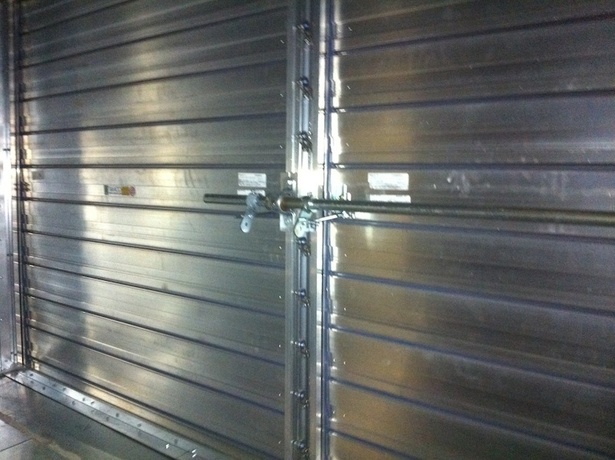
In our field we frequently deal with applications where we use wall penetrations to relieve and intake air. It could be the need for bathroom exhaust, makeup air intake, emergency purge exhaust, or even general building pressure intake or relief. For this case-study, it is for emergency generator intake and exhaust at a new-construction project for the Erie County Medical Center. If the building loses power and the emergency generators are required to kick on, the dampers will open to allow combustion airflow into the space.
For this application the dampers will be closed 99% of the time. The space within is still conditioned (heated and cooled) and energy loss through wall penetrations can be great if not properly considered with a preventative approach. This was a legitimate concern for the design engineers. The wall cavity sections at ECMC are large - roughly 100 square feet a piece. They know that in order to maintain a high-performing energy system they will need to minimize all wasted energy through this area.

 RSS Feed